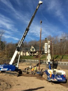
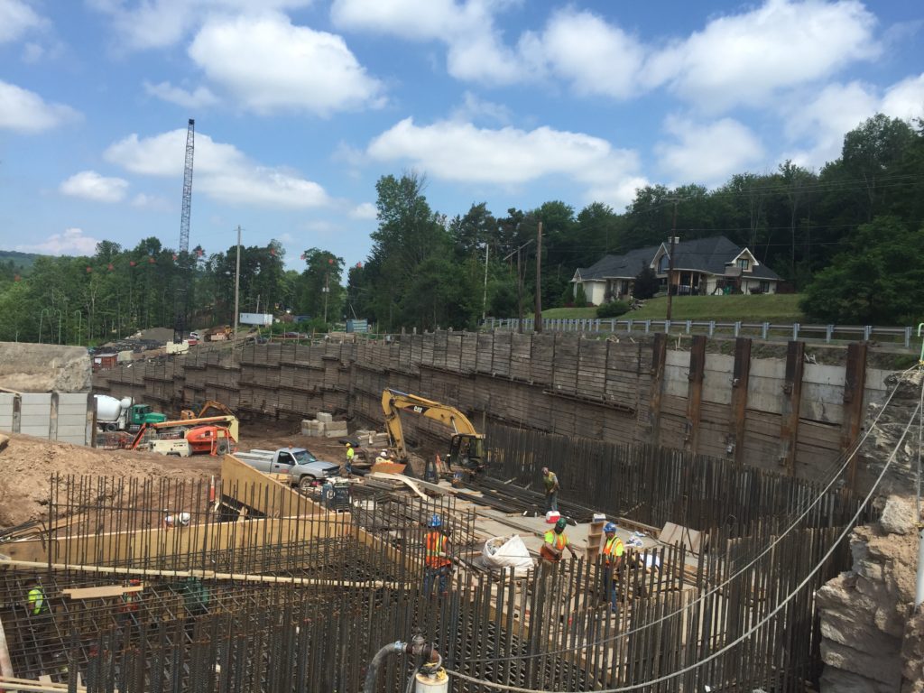
This project called for the installation of a temporary Soldier Pile and Lagging wall for soil retention for the rehabilitation and construction of a new spillway for a dam.
This project called for the installation of a temporary Soldier Pile and Lagging wall for soil retention for the rehabilitation and construction of a new spillway for a dam.
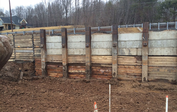
Cost effectiveness and flexible installation techniques were paramount to the project. With these criteria in mind, a soldier pile and lagging system was selected. The design engineer reviewed all available geotechnical information including core borings and unconfined compressive strength of the formation in developing the appropriate design calculations. Once mobilization to site occurred, the theoretical design parameters were validated in a pre-production testing program prior to commencing production.

The goal of this project was to install a retention system to enable access for construction of a spillway. The underlying complex subsurface conditions and site constraints lead to the utilization of a soldier pile and lagging wall.

Sq. Ft. Timber Lagging Wall

Sq. Ft. Concrete Lagging Wall

LF of tieback anchors

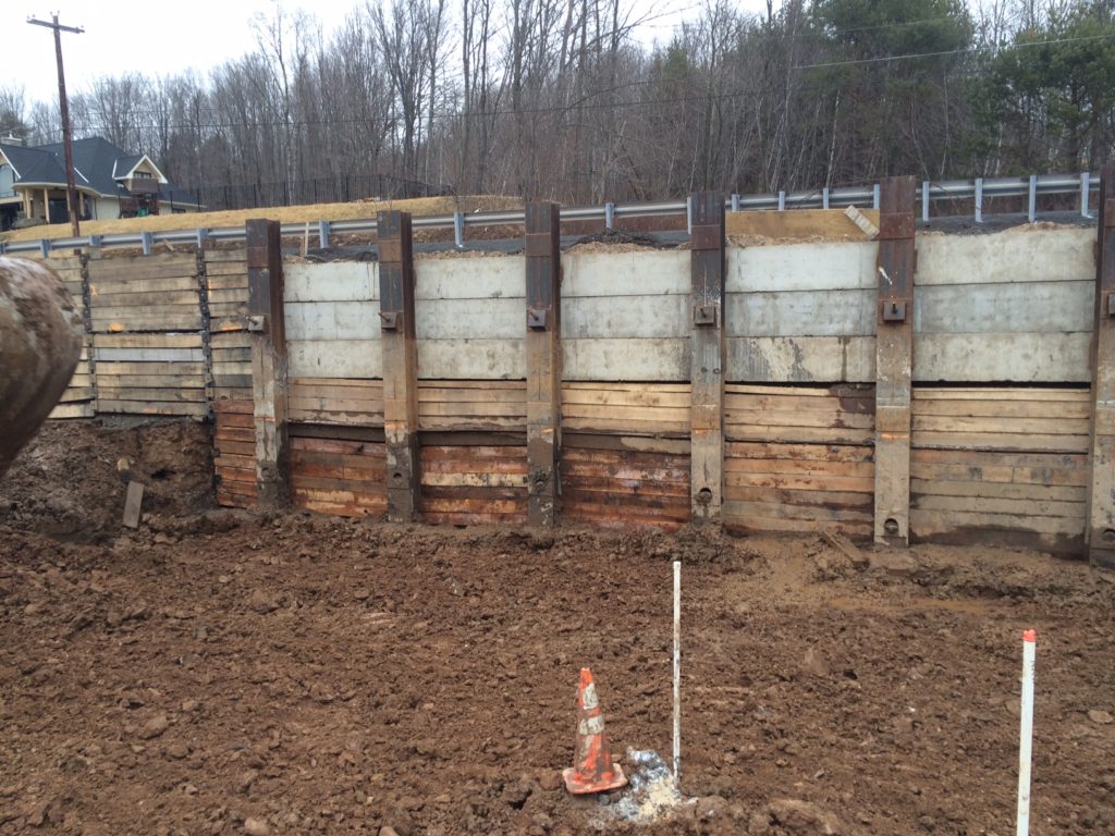
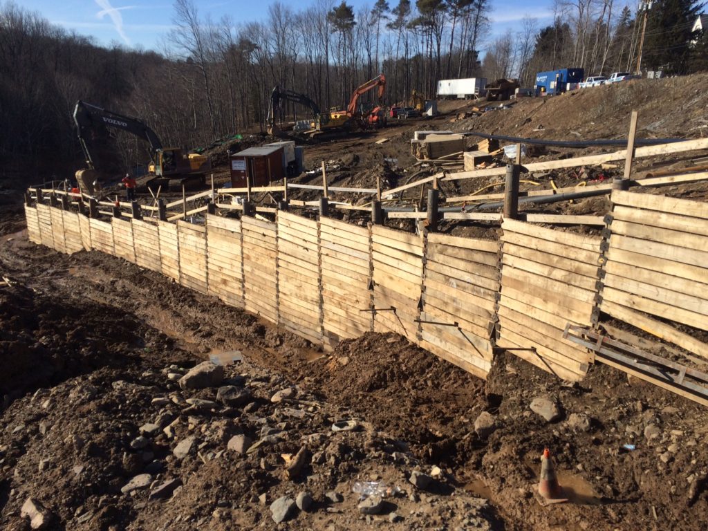
Coastal Drilling East was tasked with the installation of a temporary soldier pile and lagging wall to enable the construction of a new dam spillway. Upon mobilization to the site, the H-piles and micropile pipe piles were drilled and installed forming the perimeter of the new wall. Following the installation and grouting of all soldier pile elements, excavation commenced. The excavation was completed in maximum four to seven foot lifts, as conditions dictated, to depths of 30 feet.
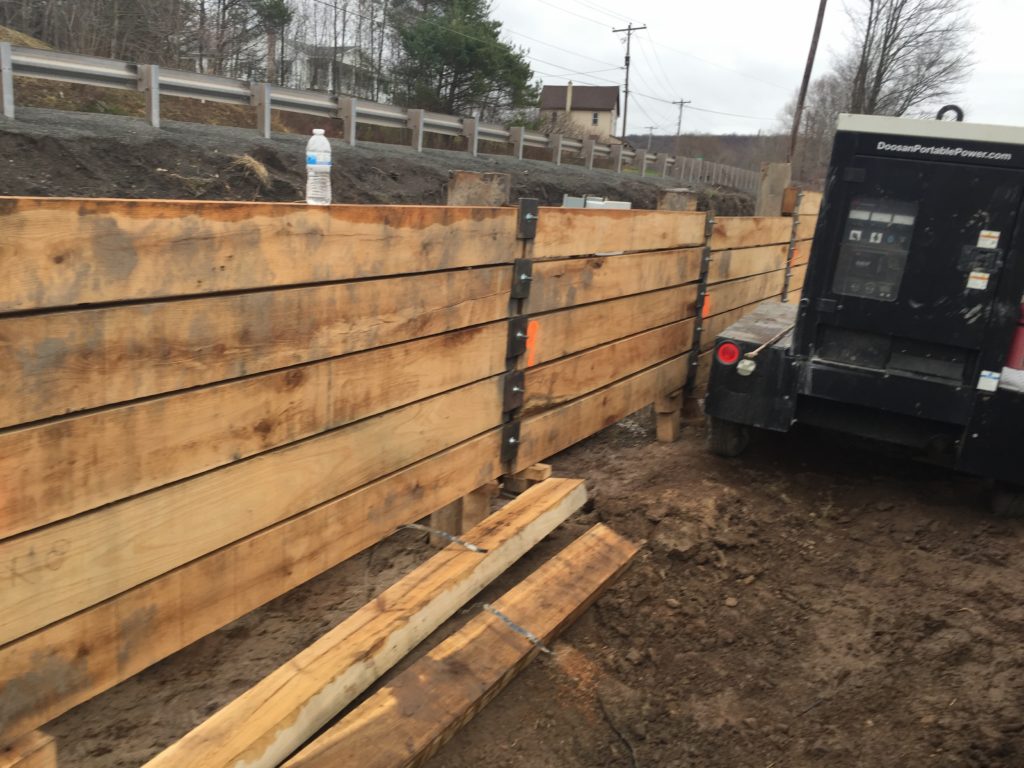
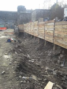
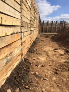
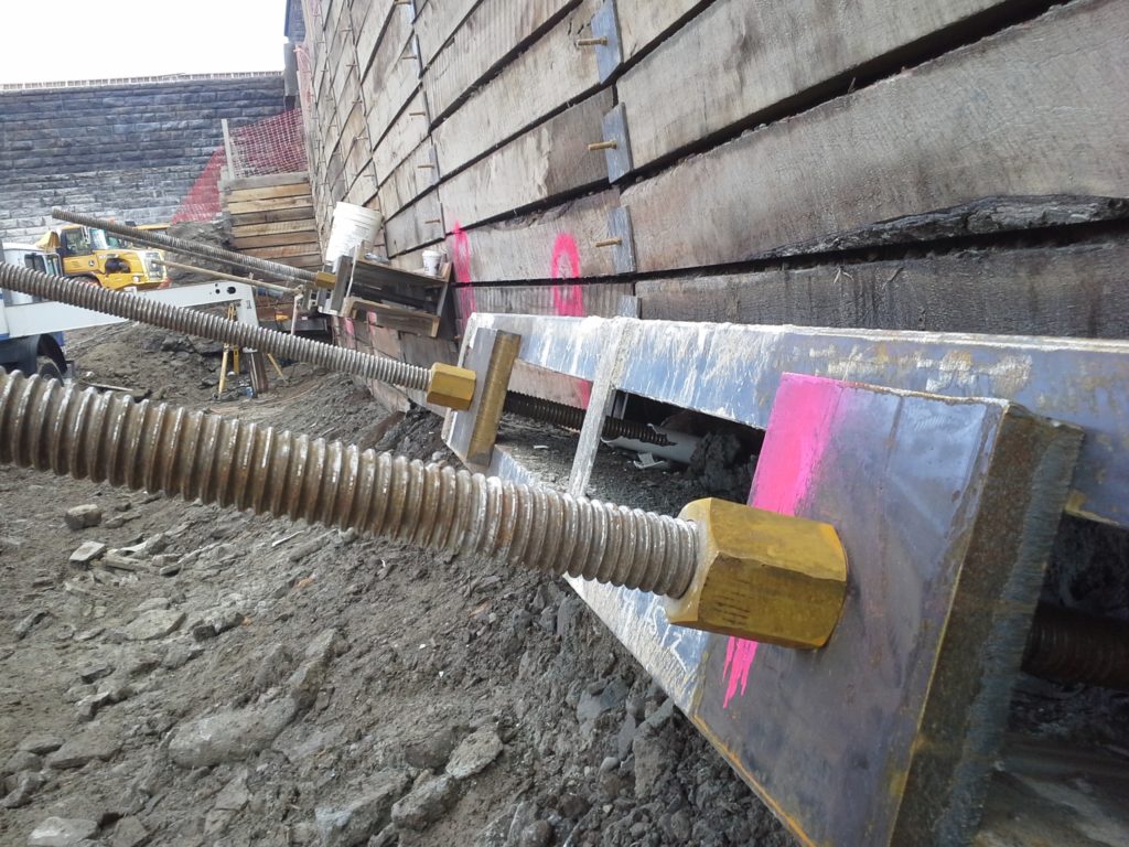
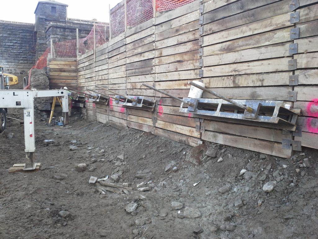
Following the excavation of each lift, lagging materials consisting of mixed hardwood timber or precast concrete panels were installed. The timber lagging materials were fastened to the piles by field welded threaded studs to the piles and attaching steel plates to hold the timber lagging in place. The tieback anchor installation began once the timber lagging was installed to the appropriate depth below the existing ground surface. The tiebacks were drilled prior to the waler installation and then the waler was attached to the beams. The tieback anchor borehole was drilled through the overburden soil to the designed depth. The tieback anchors were initially grouted during installation, but had to be post grouted as well due to soil conditions. Upon attainment of the required minimum strength, they were tested and locked off to design specifications.
